KORG microKEY modding
KORG microKEY MIDI OUT without PC or any USB host
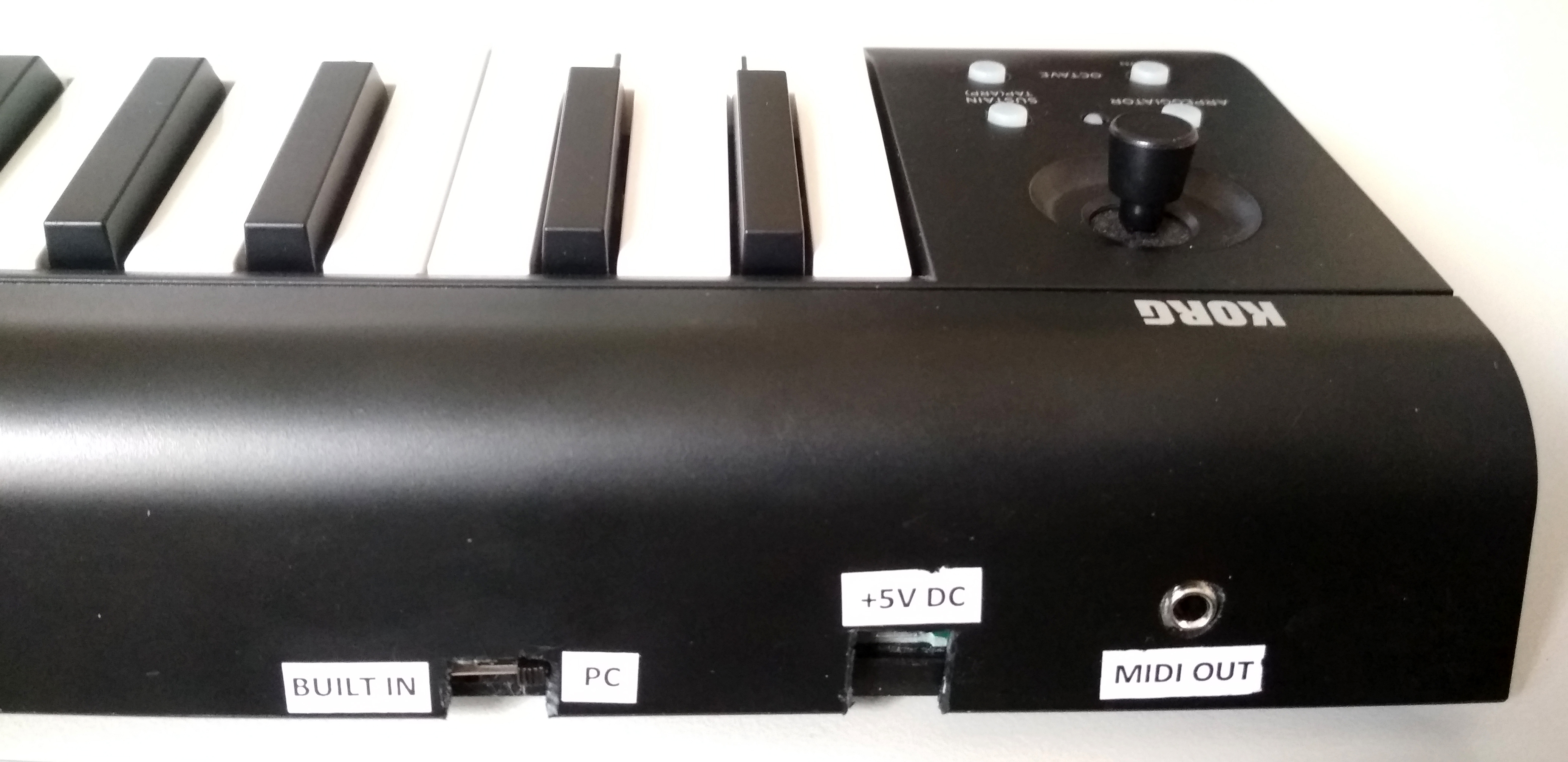
After modding my microKEY is
- got an built-in USB host;
- can work as a standalone MIDI keyboard without any PC or other USB host;
- powered by a 5V battery pack (power bank);
- has a mini jack MIDI OUT port;
The story...
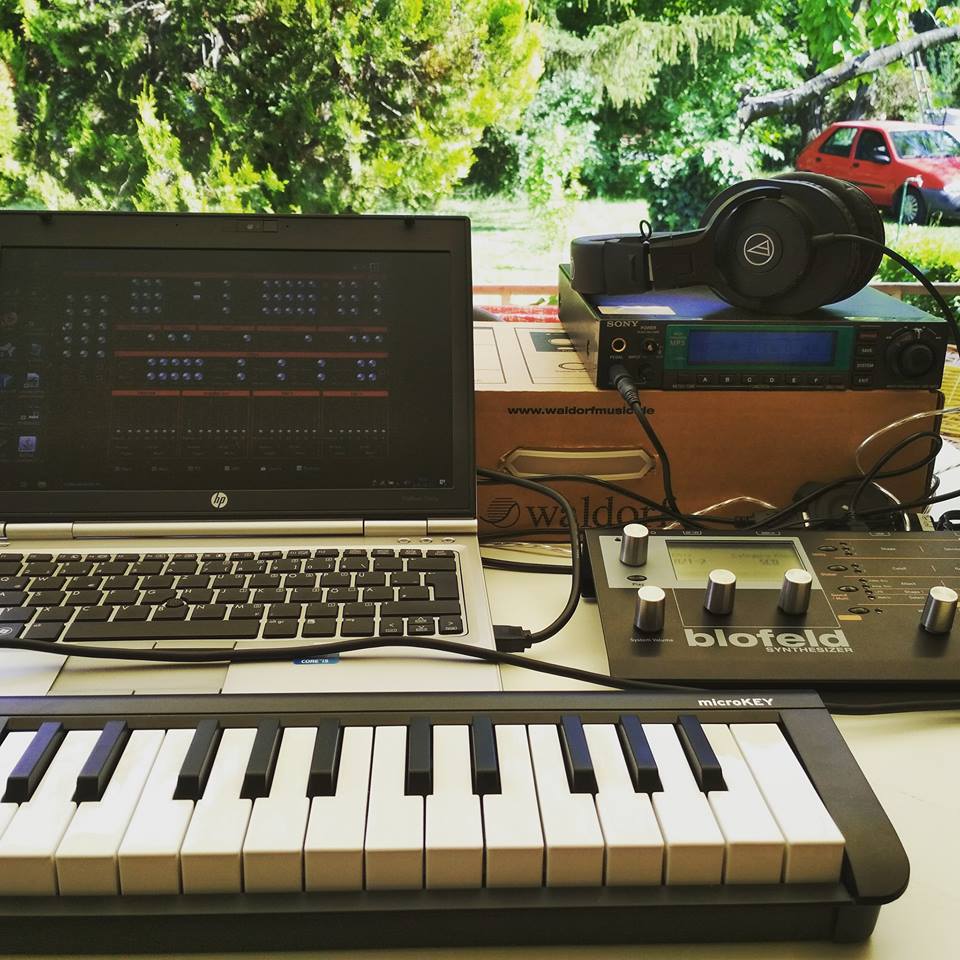
In some cases I did need a small keyboard for my synths (Blofeld, D-05) but nowadays very rear a good mini keyboard with
standalone MIDI OUT. Most of them are need an USB host (PC or MAC, etc...). Usually I don't wan't to use PC for a sunday afternoon jaming on
our balcony, I decided I'll mod my microKEY... Just imagine the following picture without the PC... ;-)
Suddenly I just find that post on the internet: DIY USB/MIDI Host
It's get my attention and I thought that that is what I'm looking for! So I ordered an USB host controller from the HobbyElectronics.
The preprogrammed microcontroller was just about 15,- Ł (GBP). I did have the other parts what are needed, but of course these are also very cheap parts...
How to...
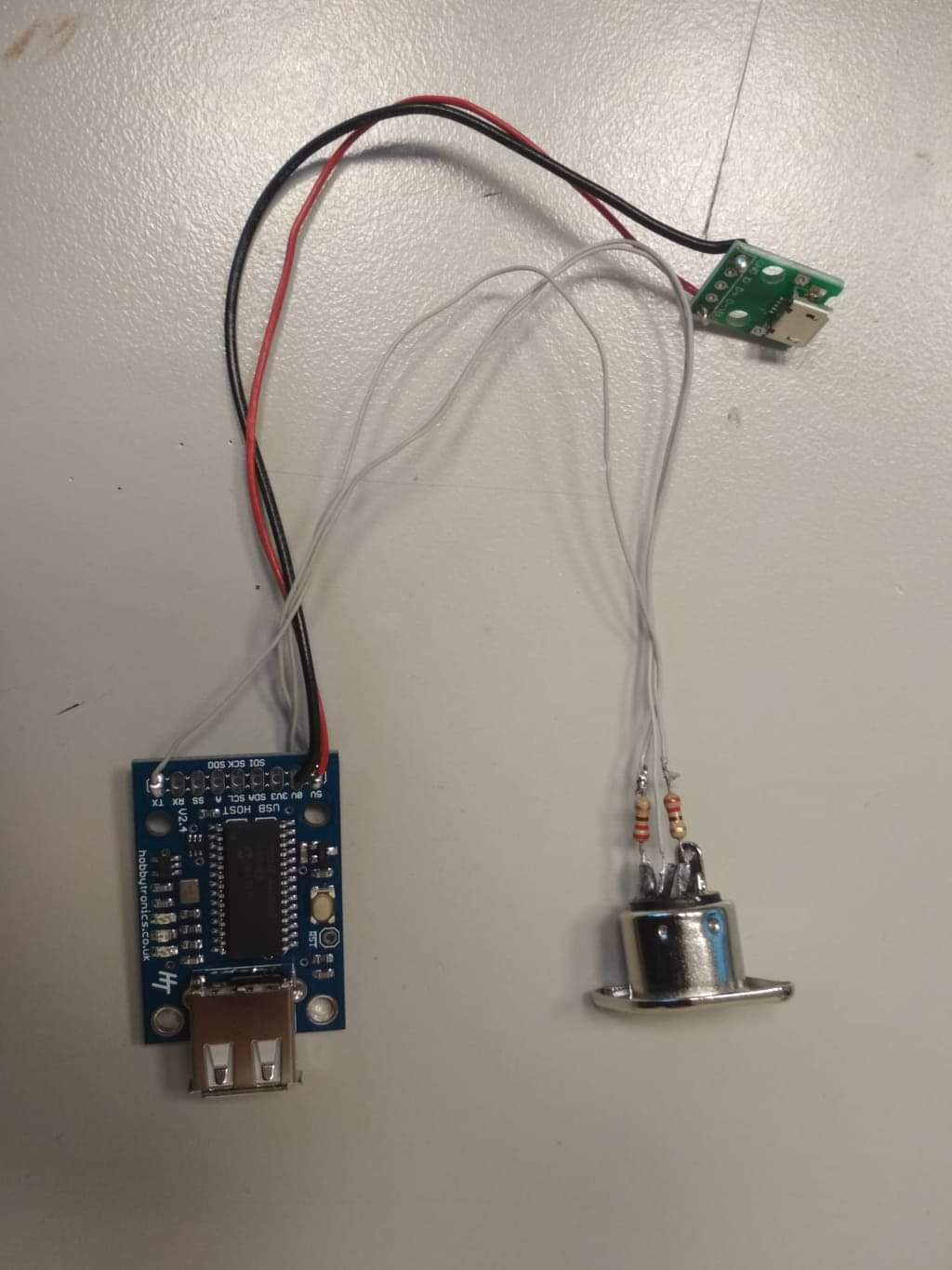
Becouse I don't need MIDI IN just MIDI OUT I don't need above the microcontroller just two of 220 ohm resistor, a microUSB female connector and a mini jack
connector (meanwhile I just found it it's not necessary... The microkey can connect to my powerbank and works across an ordinary USB cable too). Some wires, soldering and a bit drilling...
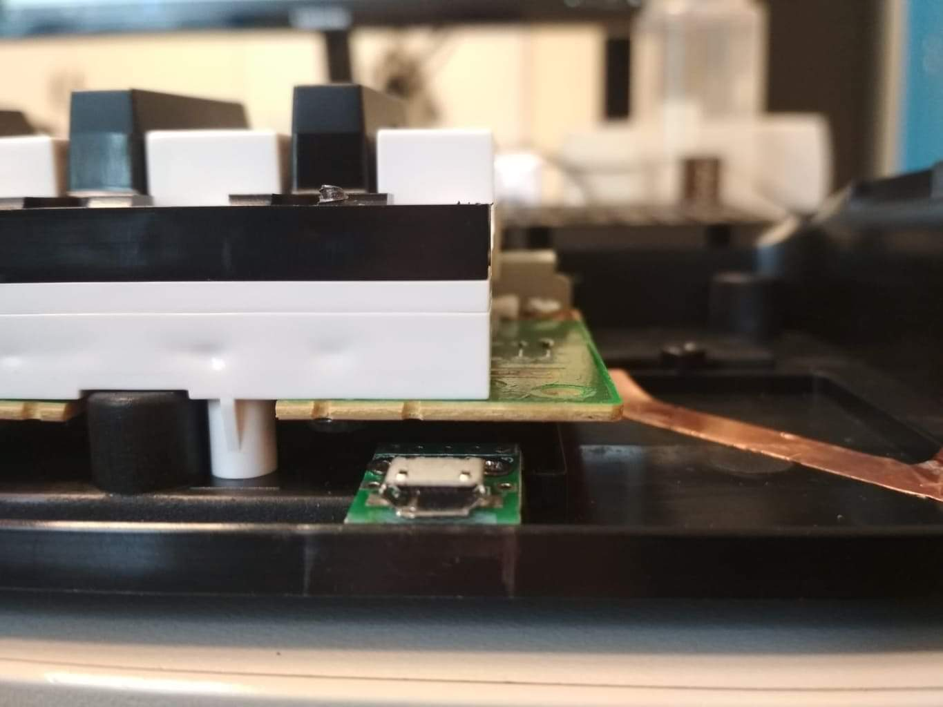
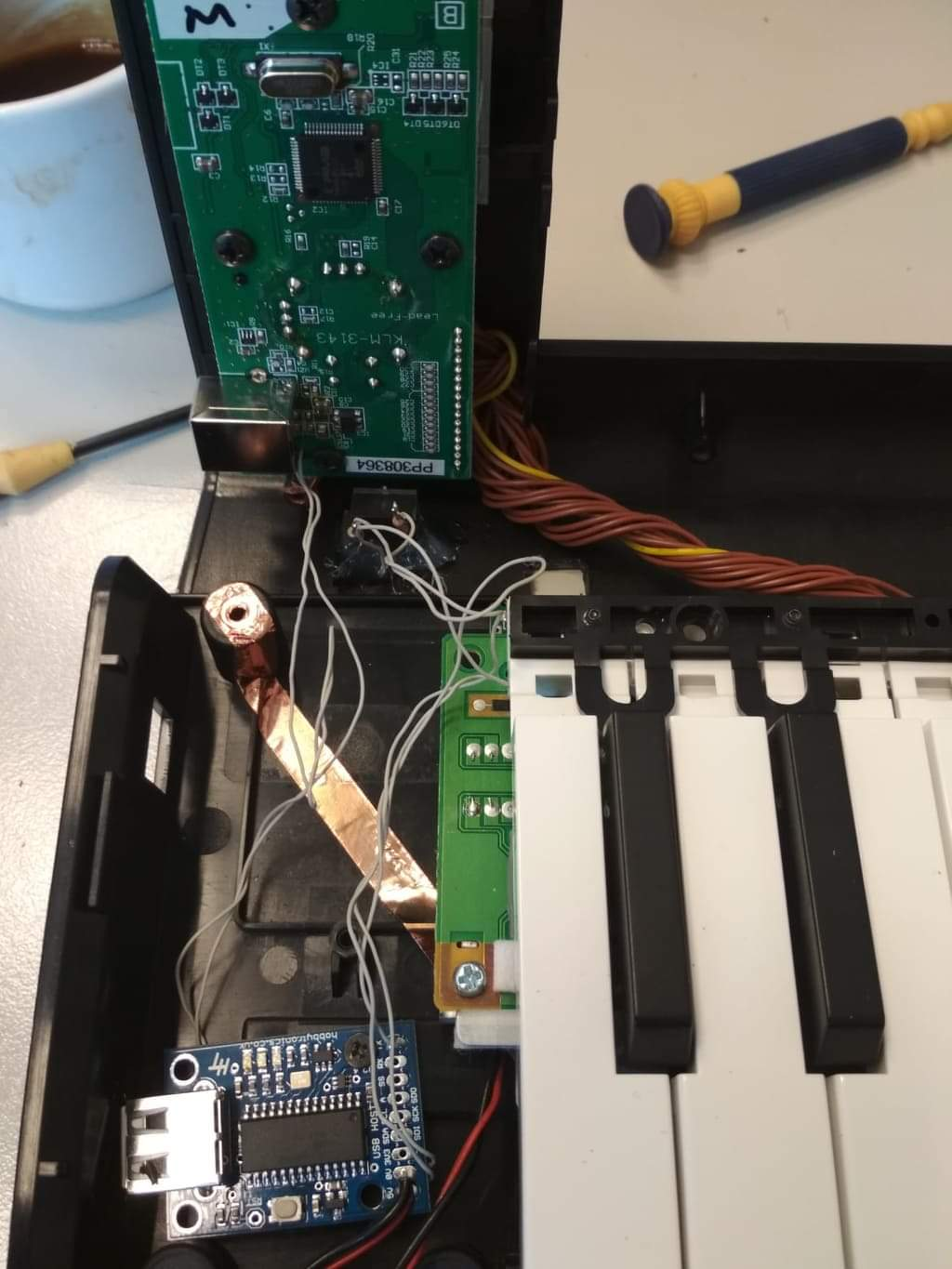
On the next picture still there a DIN5 MIDI connector, but it has not enough place inside the microKEY, so I had to changed it to mini jack.
First of all I did dismantled my microKEY to check is there enough place for all? I'm lucky, there is! :)
I searched places for the parts, then I drill a hole for the mini jack and an another for the microUSB female.
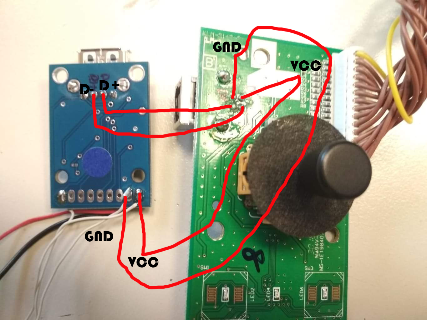
Soldering the microKEY VCC and GND points to the USB controller's VCC and GND points.
By two of wires I did connected the microcontroller's D+ and D- points to the microKEY D+ and D- points.
It's will be need a switch to deconnect the controller when you use your microKEY with a computer because your microKEY will not work on the computer when the D+ and D- lines are attached to the
controller and to the computer across the microKEYs USB connector at the same time!
I took that switch next to the microUSB connector later then I took the pictures... Sorry... But you can see it on the first picture! :)
Some soldering, wireing and that's all! :)
One more little stuff what you'll need:

The MIDI DIN point 4 is the controllers TX point across a 220 ohm resistor and TIP on mini jack, the DIN 5 point is the VCC point across a 220 ohm resistor and the RING on mini jack, and the GND
is the DIN 2 and the SLEEVE on the jack...
The microntroller itself just fixed by a screw - it's will not moving I hope, I'm usually very carefully with my instruments. ;)
Not so hard project is it? ;)
A good advice
It applies to all posts are following!
In these times the MIDI devices are built in to a 3.3V system instead of the original 5V system.
By that you should forget the old, good one optocouplers: 6N137 and 6N138 becouse these are not working well on 3.3V MIDI systems.
Use PC900 instead - it's works well with the 3.3V MIDI system devices.
Believe me! You will prevent a lot of "mystic" problem... ;)
MIDI ThruBox
a 1 IN -> 4 OUT MIDI THRUBOX
My friend asked me if I know about a cheap MIDI ThruBox?
Of course! :)
On Marc Bareielle's site there is a simple schematic. It's use an optocupler, a 74HC14 6xSchmidt trigger logic and some passive parts...

It's so simple to build, may not need a PCB just some wireing...
In this case I used one DIN5 and 4 mini jack MIDI connector, and a USB female connector to powering...
A short video about working...
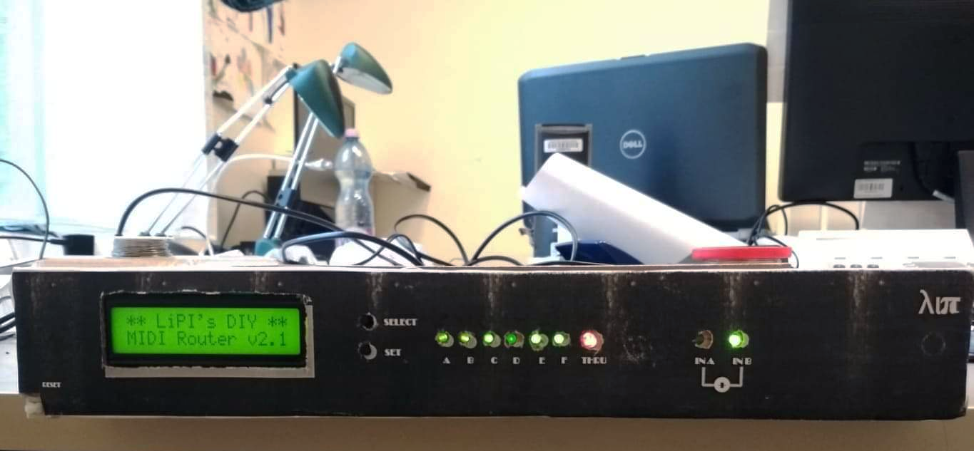
DIY MIDI Router
2 MIDI IN (merged); 1 MIDI THRU; 6 MIDI OUT;
I just built a new, expanded version of
Davide Bucci's MIDI Splitter. (Thanx Davide for your help!)
Anyway, if you decided to build his original 2 OUTPUT version, I recommend that use my firmware version
(just don't forget to edit the Number of outputs in the asm source file, then recompile it) becouse the MIDI Running Status, the System Real Time, the System Common messages and the System Exclusive message status are did not handled in the original firmware!
Mine version has 2 MIDI IN (merged), a MIDI THRU and 6 MIDI OUT ports. Each MIDI channel can addressing for A-F MIDI OUT ports.
The non channel messages are broadcasted. The system exclusive message status and data bytes are also broadcasted.
The firmware(s)
For the MIDI merger part I used the original firmware. I did not modified any on the original project, just left the unnecessary parts (LEDs, etc.)
You can find all the necessary infos and files in that archive file, or on the Thorsten Klose's site in original format and with the descriptions.
Here is the router's firmware for PIC16F876 in .asm and in .hex formats. I did made a lot of comments, so I hope you can follow my programming "brainflow"! ;-)
My developments on the firmware:
- the router now can recognize the MIDI Running Status and can handle it;
- the router now can recognize the System Exclusive status and can handle it;
- the router send the system (both the Real Time, Common and Exclusive) messages for the all OUTPUT ports (broadcasting);
- I use an 8 MHz clock source instead of 4 MHz. If your PIC will "buggy" at 8MHz you have to use 4MHz clock instead of 8 MHz. Mine fortunatelly running stable. In the archive file you find the both version in hex format!
- I have to add "dummy text" for the asm source, becouse the bigger interrupt routine there was overlapped memory areas... (
as you can see in that short video in the "Selection Mode")
- I use a RC1602B-GHY-CSXD display, so I need more time in some places for wait for the display. Anyway it does not needed to grounded the all upper bits, just the 5th!;
Here is the Schematics in pdf format
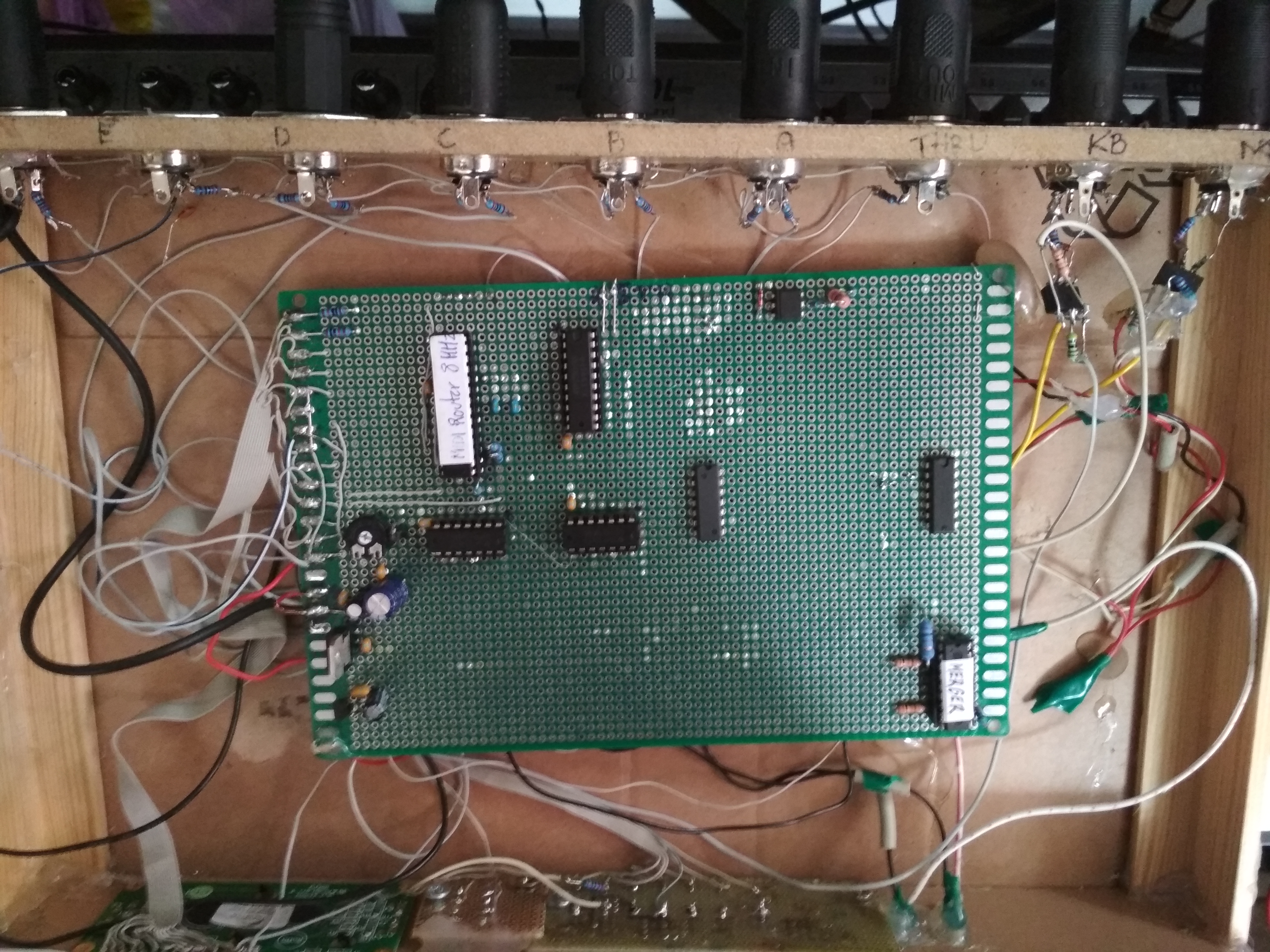
Some pics about the prototype:
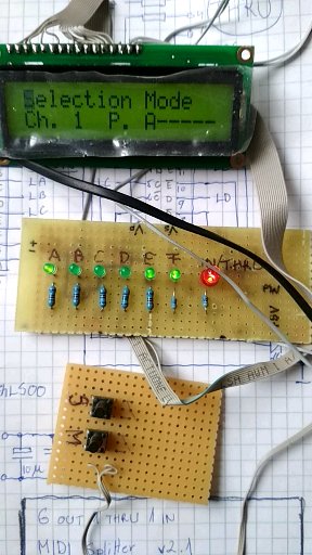
A bit chaotic becouse I made it on a test panel, but hey, it works! :) Anyway yes, there is some unnecessary chips on board...
I was lasy to soldering out the unnecessary optocoupler and Shmidt trigger... :-P
The mergers' optocouplers are soldered to the DIN connectors... Not so elegant... but it's a prototype as you know ;-)
In my studio setup
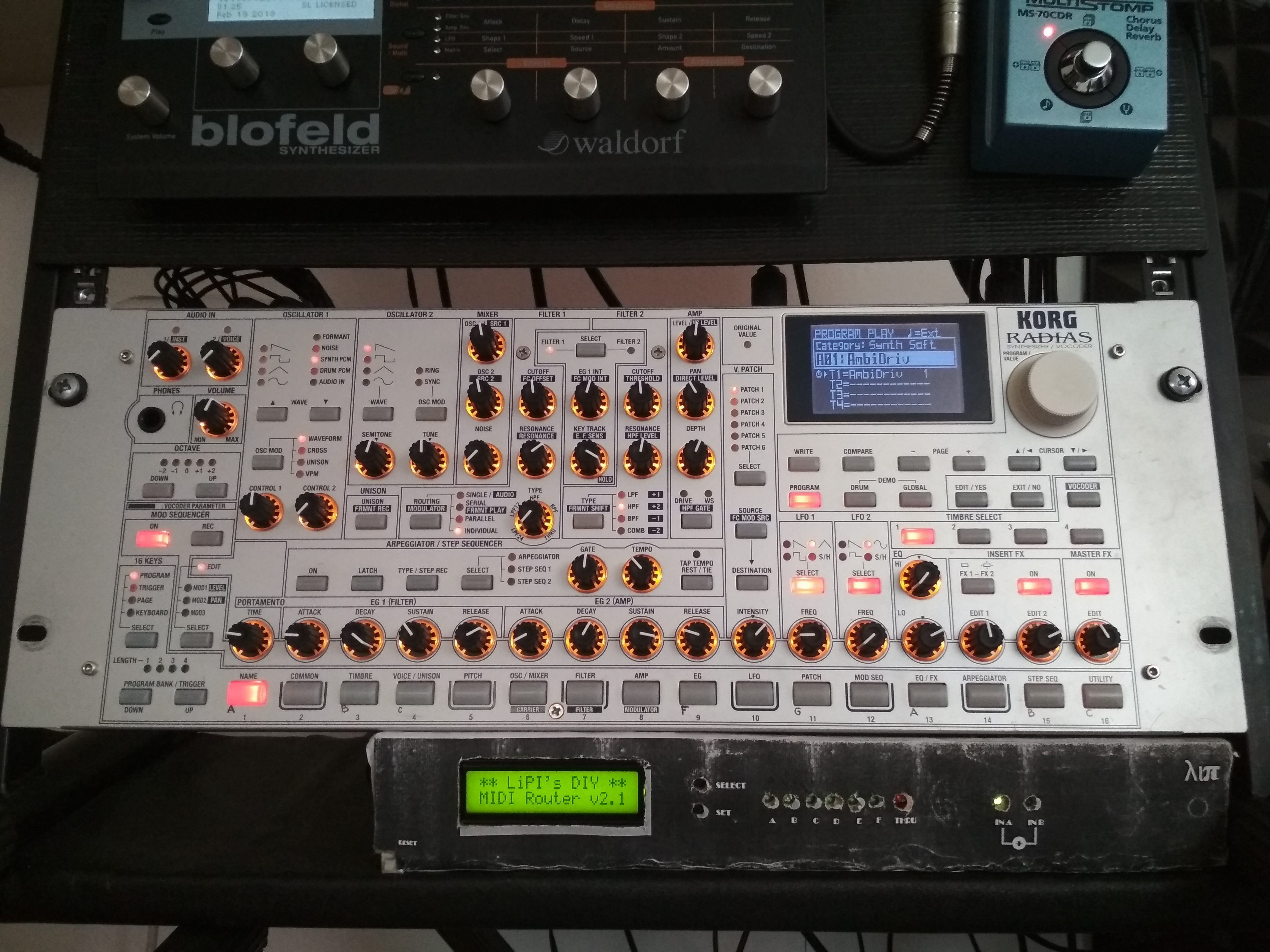
I plan that I'll build it in a rack unit box - it's will be so nicer! :)
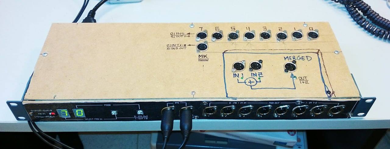
DIY MIDI Patchbay + MERGER
A long time ago I owed with this short briefing about my DIY MIDI PatchBay + MERGER.
It's based on M. Bareielle's MIDI Patch bay. My patch bay has a Thorsten Klose's PIC16F88 based MIDI merger,
and some days ago I complement it with an other independent MIDI merger (also based on PIC16f88) block for my best usage.
The MIDI merger basic synoptic is the follow:
 IN7..0 : One of these are selectable by the SELECT switch; the selected INPUT is routed OUT to the INSOUT in MODE0, and to the OUT1..8 ports in MODE1. These ports are not merged in the patchbay.
(1..8 on synoptic)
IN7..0 : One of these are selectable by the SELECT switch; the selected INPUT is routed OUT to the INSOUT in MODE0, and to the OUT1..8 ports in MODE1. These ports are not merged in the patchbay.
(1..8 on synoptic)
MKIN : Input for master keyboard, master CLK, etc. This input is always merged with INSIN port! In MODE0 routed to the OUT1..8 ports. In MODE1 routed to the INSOUT port.
IN1, IN2 : MIDI input ports for the individual MERGER. (Not present on synoptic)
OUT : MIDI output with the merged IN1 and IN2 data flow... (Not present on synoptic)
INSIN : Input for sequencer(out)/sysex usage; this port is always merged with the MKIN port! In MODE0 routed to OUT1..8, in MODE1 routed to INSOUT.
INSOUT: Output for sequencer(in)/sysex usage; in MODE0 represent the selected IN7..0 port; in MODE1 represent the merged MKIN and INSIN data.
OUT1..8: Output ports. These ports are like a MIDI THRUBOX out ports... It's mean that the MIDI signals are same on both ports in same time. In MODE0 these ports are repesents the merged MKIN+INSIN, in MODE1 these ports are represents the selected IN7..0 port.
MODE : button. This change the MIDI routing mode. It has two stages 0 or 1.
SELECT: button. This choose (activate for input) a port from IN7..0.
In my MIDI setup I mostly use the MODE 0.
And how is everything in my studio it's also changing times to times of course... :)
In MODE1 I can use the PCR-800 as master keyboard for PC/DAW and I can represent the DAW's sequence on the synths (RADIAS and MC-808). It's ideal for sysex usage and/or track by track recording.
